Hyperklean provides annual safety checks to ensure that the system is performing to the standard requirements, repair any issues found with the fire damper or install a new replacement Fire Damper.
Some of our clients have in excess of 2000 fire dampers, others have only a few. Regardless of the numbers, our robust reporting system allows our clients to analyse the fire dampers inspected, track both historic and future inspection dates, and view a comprehensive report including photos for every single fire damper inspected.
Fire dampers are vital safety systems installed within ducting ventilation designed to prevent the spread of fire and or smoke throughout a full system. Hyperklean provides annual safety checks to ensure that the system is performing to the standard requirements, repair any issues found with the fire damper or install a new replacement Fire Damper.
Some of our clients have in excess of 2000 fire dampers, others have only a few. Regardless of the numbers, our robust reporting system allows our clients to analyse the fire dampers inspected, track both historic and future inspection dates, and view a comprehensive report including photos for every single fire damper inspected.
The Building Engineering Services Association have released a technical bulletin relating to fire and smoke damper maintenance (VH001). Please get in touch if you require a copy of the document.
The objective of the technical bulletin is to inform both BESA members and Building Owners/Managers of specific considerations when testing and maintaining fire and smoke dampers. It should be used alongside:
- BESA publications: DW/145: Installation of Fire and Smoke Dampers;
- DW/144: Sheet Metal Ductwork;
- TR/19®: Internal Cleanliness of Ventilation systems and
- TR19® Grease: Fire Risk Management of Grease Accumulation within Kitchen Extraction Systems.
- Reference should also be made to BS9999: Fire safety in the design, management and use of buildings,
- HTM 03-01: Heating and ventilation of health sector buildings
- HTM 05-01: Managing Healthcare fire safety.
- VH001 – Fire and Smoke Damper Maintenance, will be incorporated into the BESA publication DW/145 – Installation and Maintenance of Fire and Smoke Dampers, currently under review
STANDARDS
BS 9999 provides a best practice framework for fire safety and includes standards for the definition, maintenance and testing of fire dampers. It states that all fire dampers should meet the criteria of fire resistance for a stated period of time and that: “All fire dampers should be tested by a competent person at regular intervals not exceeding one year, and to be repaired or replaced immediately if found to be faulty. Spring-operated fire dampers should be tested annually and fire dampers situated in dust-laden and similar atmospheres should be tested much more frequently, at periods suited to the degree of pollution.”
In addition; guidelines have been introduced by the department of health that encourages regular testing of fire dampers. In Part B of Health Technical Memorandum HTM 03-01, fire dampers are required to be tested and maintained annually.
Spring operated fusible link dampers
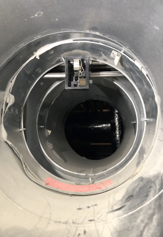
Spring operated fusible link fire dampers are commonly designed to activate when the temperature exceeds the limit (typically 72° C). The fusible link releases the spring loaded fire damper to contain the fire within the ductwork space. This ensures that the fire does not spread through the ductwork ventilation system. BS 9999 defines a fusible link as a “device that releases a component such as a fire damper or fire shutter at a set temperature”
TESTING
Prior to testing a full risk assessment should be carried out. Where dampers are fitted, specific considerations should be given to accessibility in small sized ducts. All contractors need to have sufficient training to carry out maintenance work. Testing should include, but not limited
to the following steps:
- an inventory of all dampers to be tested
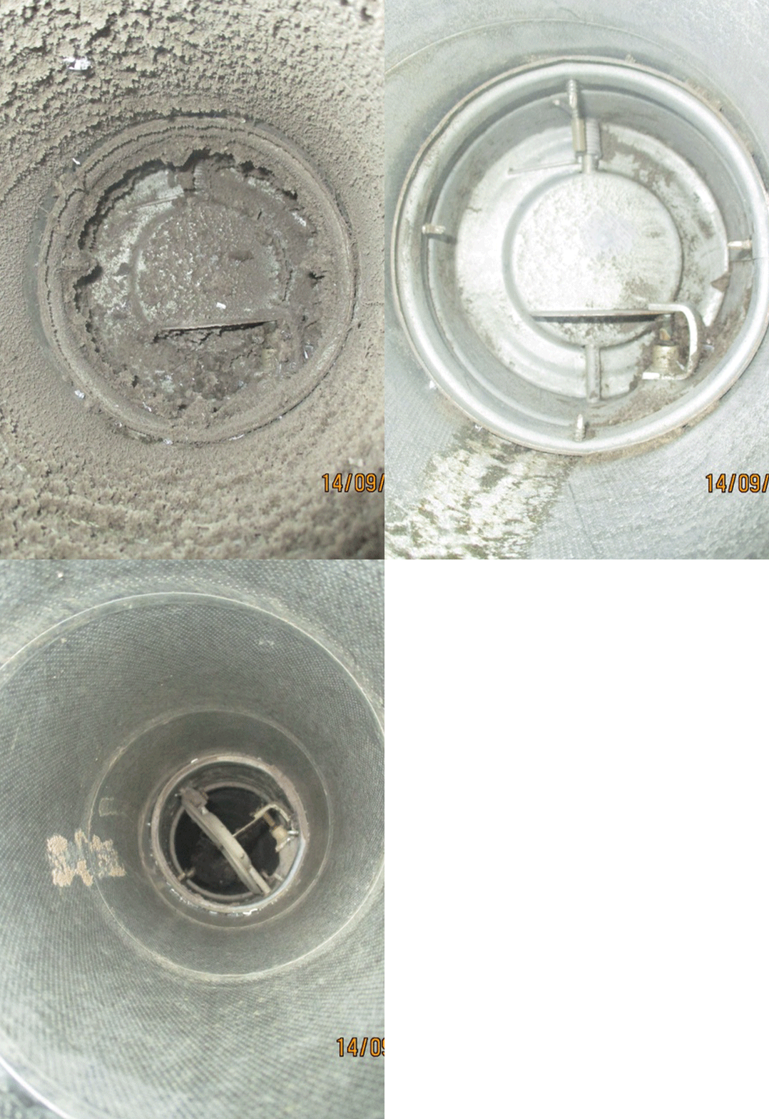
- all manually resettable dampers will be released to ensure the integrity of the spring loaded shutter. On motorised fire dampers the control mode should be operated to ensure that the blades are moving from the open to the closed position and vice versa
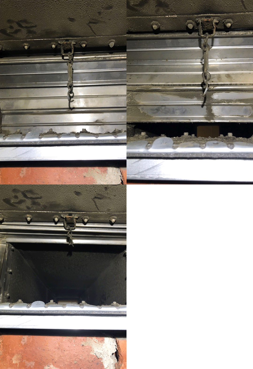
- the Fusible link should be inspected for any deformity or damage
- the fire/smoke damper will be cleaned
- the fire/smoke damper shall then be opened and re-set
- A review of the previous inspection report to check if
any modifications have been made, outstanding remedial actions have been completed
REPORTING
Reports should include, but are not limited to:
- test results with client information including position within the building/system, date, and name of operative shall be recorded and any comments noted if further action is required
- asset register to include damper location and ID number
- Where the damper is not fully or only partially accessible due to inadequate access either in
ductwork or the building fabric it must be reported to the client and remedial action reccomended. - inspection results including details of failed damper operation
- explanation of failed operation and recommended corrective or remedial action
- if a fusible link has failed it should be reported to client who must take remedial action
- any severe corrosion or damage found shall be reported to the client
- if drawings are provided, update and annotate details
- digital photographic evidence of damper condition prior to and after testing procedures
- visual assessment of fire stopping integrity and/or damage observed to immediate area of fire damper
- damper fixing should be checked as far as is practicable to be in accordance with manufacturer
specification, for example – drop rods fixed to securing lugs on damper frames / correct riveted fixing of duct to damper frames and damper fixing to the wall - fire and smoke damper closure to be checked to correctly indicate on the relevant fire panel where
applicable - where lubrication is required the damper manufacturer’s specific instructions should be followed or, in the absence of these, a PTFE lubricant should be used to minimise adhesion and dust

INSTALLATION
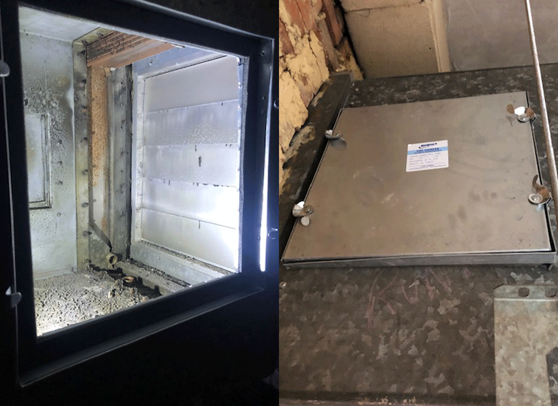
To enable the Fire Dampers to be tested and reset access panels need to be installed. Access panels shall be quick release insulated sealed panels, all manufactured and installed to BESA specification DW/144. Required location of the access panel, along with the party responsible for the provision of the panel is prescribed in Table 3 of BESA publication TR/19®
Kitchen Extract Ventilation
Fire dampers should not be fitted (BS 9999:2017 Clause 32.5.2.2 and 32.5.4). Where fire dampers are still found in older installations, these systems should be tested annually, as a minimum, as required by BS 9999, or removed from the system entirely. Removal is recommended and will require a review of the fire risk assessment
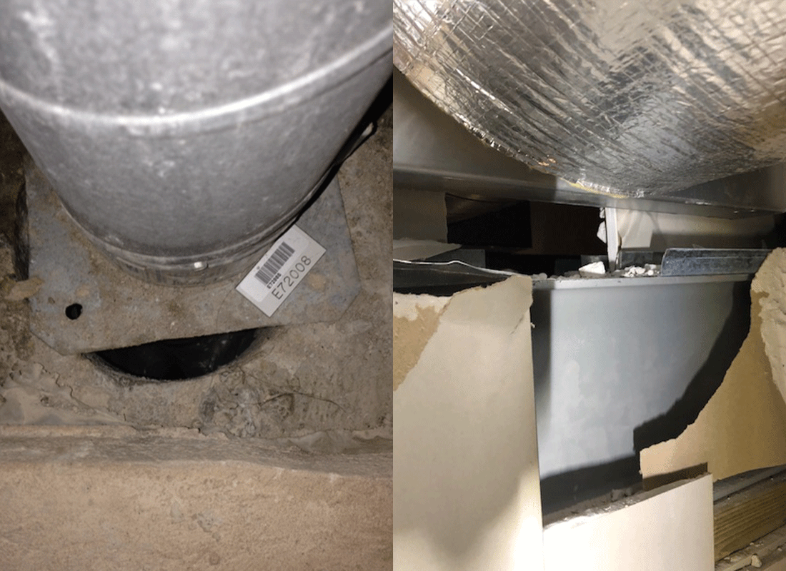
Fire Stopping
The penetration seal between the damper and structural element often referred to as “Fire stopping” materials and include, but are not limited to, vertical or horizontal builders work structures, dry-lining partitions and vertical fire blankets. The penetration seal is used to restore
and maintain the fire classification of the fire separating element/barrier at the position where the damper/ductwork pass through the barrier. The penetration seal must be installed in accordance with test methods for use when penetrated by a damper

- Installation Frame – Designed to integrate the damper into the partition. Available as a HEVAC or plate frame.
- Link Bracket – Retains the fusible link.
- Fusible Link – Retains the Blade pack in a recessed position under normal operating conditions. Splits into two parts to release blades upon reaching rated temperature (usually 72oC), this ensures the fire does not spread through the ductwork ventilation system.
- Blade Pack – Interlocking steel blades which concertina into the header during normal operating conditions. When the fusible link splits the blade pack is pulled closed by the blade springs.
- Case – The main body of the damper, comprising elements including the header and spigots.
- Lock Guide – Two fitted to each damper, act to retain the blade springs and also lock the blade pack in position when closed.
- Blade/Flat Coil Spring – Fully extended during normal operation. When the fusible link splits, the blade springs pull the blade pack down and into the lock guides.
LEGISLATION
With the enactment of the Regulatory Reform (Fire Safety) Order 2005, it is now the employer’s responsibility to maintain their fire safety systems. BS 9999 Annex W.1 Inspection and Maintenance (Note 2), also states that: ‘Arrangements should be made for all fire dampers to be tested by a competent person on completion of the installation and at least annually, and to be repaired or replaced immediately if found to be faulty.’


